An LED display adapted for DIY projects
- Analog
- 2023-09-23 21:19:13
This expandable LED display for a microcontroller in Figure 1 has a simple interface with only 6 data/control wires and can be easily accommodated to a DIY design. The display has static indication.
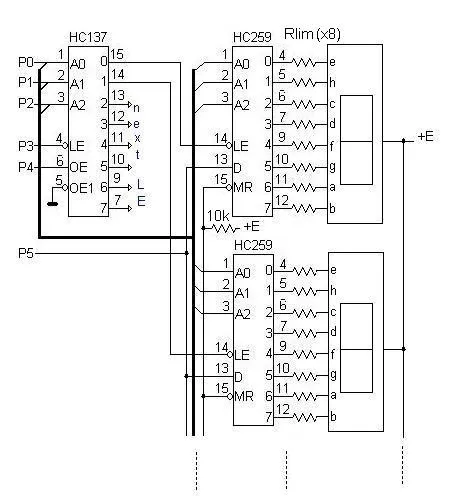
Figure 1 The expandable LED display for a microcontroller has a relatively simple interface with only 6 data/control wires.
Wow the engineering world with your unique design: Design Ideas Submission Guide


The main parameters are:
Digits: 8 Hex digits (may be more, expandable)Data & control wires: 6 (minimum)Power voltage: 3…6 VPower consumption: < 3…5 mA/digit (Rlim in range 2 k – 2.4 k for E = 3,3 V or, Rlim in range 4.3 k – 5.1 k for E = 5 V)If you choose the segment current too low (lower than ~0.7 mA) some segments may become much darker than others. For this reason, it would be wise to check the performance of your indicators with the low current.
The circuit in Figure 1 is optimized for 7 segment indicators such as the A-522SR (dual, with common anode and super-bright LEDs) and DIP versions of the 74HC259 (8-bit addressable latch) and 74HC137 (decoder).
By placing the pair latch/indicator in close vicinity to one another, we can strongly reduce not only the dimensions of the display, but the amount of soldering as well. This characteristic makes the circuit very suitable for DIY designs. In this design, we can solder the Rlim resistors (SMD 0805) directly between the corresponding legs of the latch and indicator. The pin assignment is shown for this case.
The algorithm of the interface:
0. Initial/displaying state: P3=1, P4=0, all other pins are of no importance;
The steps required to change the data on the display are:
1. Set a digit’s address: P2..P0 = address;
2. P3= negative strobe 1-0-1 to latch the address;
3. Set a segment’s address: P2..P0 = address;
4. Set a value of D: P5=0 if the segment must be ON, P5=1 if OFF;
5. P4= positive strobe 0-1-0 to latch the value of D;
6. Repeat from (3) for the other segment, when all the segments are done, go to (1) while there are unattended digits.
This principle can be expanded for more digits simply using an analogous decoder with more legs.
—Peter Demchenko studied math at the University of Vilnius and has worked in software development.
Related Content
LED current regulator has low dropoutA safe adjustable regulatorExtending the resolution of a peripheral DACShunt circuit clips large transients or regulates voltageHow to design LED signage and LED matrix displays, Part 1My seven-segment LED-dimming mysteryAn LED display adapted for DIY projects由Voice of the EngineerAnalogColumn releasethank you for your recognition of Voice of the Engineer and for our original works As well as the favor of the article, you are very welcome to share it on your personal website or circle of friends, but please indicate the source of the article when reprinting it.“An LED display adapted for DIY projects”