Using classic 3
- Analog
- 2023-09-23 21:19:24
When parts have been around as long, and in such widespread use, as the venerable LM317 and LM337 (and their siblings), you tend to think every trick that can be played with them is already in the (data)book. So, when the question arose whether these extremely well understood parts, that are always described in their respective data sheets as exclusively series regulators, might somehow be connected up to achieve a shunt topology, it seemed pretty far-fetched. Consequently, the possibility of the circuit in Figure 1 came as a surprise. The chip internal schematic is helpful in understanding how this monstrosity works.
Wow the engineering world with your unique design: Design Ideas Submission Guide
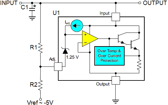
Figure 1 Three terminal regulator (e.g. LM317) in the (positive) shunt configuration.


When connected as shown, the standard “three leg” will begin to conduct as INPUT current is brought from zero and Vout approaches the programmed setpoint voltage Vset, causing Vadj to approach -1.25V. This causes the internal Zener cathode to therefore rise to 0V, and the internal regulator control amplifier to turn on the internal Darlington pass device. These design equations will then apply:
Let Vref << -1.25, e.g., -5Vset = -(1.25 + Vref)(R1 / R2) – 1.25R1/R2 = (Vset + 1.25) / -(Vref + 1.25)R1 = R2(Vset + 1.25) / -(Vref + 1.25)
When Vset is attained, U1 transitions to a very low-impedance (single-digit milliohms) super-Zener-like mode, as shown in Figure 2 and clamps Vout to the programmed setpoint. Note the absolute value marks that show the circuit can accommodate both I/O voltage polarities with appropriate choices for U1 and Vref.

Figure 2 Shunt mode I/V curve; when the programmed setpoint voltage Vset is attained, U1 transitions to a very low-impedance and clamps Vout to the programmed setpoint.
For a specific design example, let:
Vset = 12VU1 = LM317Vref = -5VR2 = 1k
Then:
R1 = R2(Vset + 1.25) / -(Vref + 1.25) = 1k(13.25) / -(-3.75) = 3.5k
Negative polarity regulation can be accommodated by doing the following:
Replace the LM317 with a LM337Replace the negative Vref with a positive VrefNote the max/min absolute value of 40V > Vset > 3V and 1.5A > Iinput > 10mA per 317/337 regulator datasheet specs.
C1 may be required for dynamic stability. See datasheet recommendations.
Stephen Woodward’s relationship with EDN’s DI column goes back quite a long way. Nearly 100 submissions have been accepted since his first contribution back in 1974.
Related Content
Adjustable regulator trimmer simple failsafe circuitSimple circuits reduce regulator noise floorPower Zener using the LM317An inexpensive, precision power supplyUsing classic 3由Voice of the EngineerAnalogColumn releasethank you for your recognition of Voice of the Engineer and for our original works As well as the favor of the article, you are very welcome to share it on your personal website or circle of friends, but please indicate the source of the article when reprinting it.“Using classic 3”